4.1 Task
4.1.1 Introduction to Task
- Each task is composed of name, priority, time interval, and watchdog. You can define these parameters of the current task yourself. The execution of different parts in a program is controlled through "task". You can define multiple different tasks to control different programs. It provides periodic or triggered execution of a set of procedures.
- The task has the ability to write the I/O mapped Output global variable to the %Q output image register, write the %I input image register to the I/O mapped input global variable, and call the execution program.
- Input image register: It is a window for PLC to receive external input switching signals. It is a storage area opened for the input signal status.
- Output image register: a storage area opened for the output signal status
4.1.2 Classification of Task
Continuous loop task
- There is and only one
- A continuous loop task means that every time the task is executed, if the CPU processing power is available, the system will trigger the task call again.
Event triggered task
- Event-triggered tasks: Acyclic execution tasks triggered by time can be classified as event-triggered tasks. Event triggering can trigger event triggering based on PLC events, determined time event triggering, hardware scan event triggering, system event triggering, etc.
Start task (Trigger task table number 1): When changing from stop mode to running mode, complete the STARTUP self-test, complete the initialization of global variables, initialize the user program error task and execute the timeout task, immediately trigger: STARTUP task, and then all other TASK initializes, then starts the continuous loop task, and then starts other tasks.
- The specific event-triggered tasks are summarized in the following table:
| Serial number | Event triggered task | Priority (default value) | Classification |
|---|---|---|---|
| 1 | PLC mode from STOP to RUN | 29 | Start TASK |
| 2 | Execute once on a specified date (specify in an independent form using date and time) Execute at a specific interval (such as every 8 hours, every day, every month) | 5~ 29 | Time event TASK |
| 3 | Execution timeout | 5~29 | Task execution timeout TASK |
| 4 | Programming error | 5~29 | Program error TASK |
- When each event-triggered task is added, a system program in the task interface format will be automatically added and placed in the first calling program of the task. The relationship between the task and the program is weakly coupled (it will be automatically added and associated, but the user can individually Delete, modify and not associated with deletion or modification)
- Task verification starts from the first enable
- Users can modify the name and order of programs, but must ensure that the first called program conforms to the interface format
Fixed period cycle task
Periodic recurring tasks are tasks that the system triggers every cycle time set by the task. The startup time is the moment when the PLC mode switches from the stop state to the running state. If there are multiple periodic cycle TASKs, the system calls them in sequence according to the priority.
- Default behavior of periodic tasks:
-
Settable cycle time range: 1ms~60000ms (maximum cycle 1 minute)
-
The default cycle time of the first established regular cycle task is 20ms, priority 10 (can be modified)
-
By default, the shorter the task cycle time is, the higher the priority the system recommends (can be modified)
-
- Baosky PLC stipulates that the maximum total number of tasks is 25, and each type of tasks is stipulated as follows:
- The maximum number of periodic recurring tasks is 9;
- The maximum number of continuous loop tasks is 1;
- The maximum number of time-triggered tasks is 15;
- Post-processing of periodic cyclic tasks is not recommended. Because it may cause tasks with the same or lower priority to be overloaded
4.1.3 Task Priority
- Priority: The order of CPU resource allocation refers to the priority of tasks. Processes with higher priority have priority execution rights.
- Tasks have a fixed dependency on priority
- The priority setting of the task establishes the scheduling priority of the relevant TASK. Baosky PLC scheduling and task priority can be set to a total of 32 levels (a number between 0 and 31, 0 is the highest priority, the higher the value) The lower the priority, 31 is the lowest priority)
- The number of optional priorities for different task types is shown in the following table:
| Task type | Optional priority | Notes |
|---|---|---|
| Fixed period recurring tasks | 5-25 | Tentative |
| Event triggered tasks | 5-29 | Tentative |
| Continuous cycle tasks | 30 | Tentative |
- If the same input is used in different tasks, the input may change between tasks. This happens when a task is interrupted by a task that also has a higher priority and causes the process image to be read again.
- Using the same input and output in multiple tasks does not make sense and can lead to unexpected reactions in some cases.
4.1.4 Task execution rules
- One task can call multiple programs, and the maximum number of called programs for each TASK is 99
- TASK is called by the system, and the main program is called by TASK
- Under the same PLC, all TASK names cannot have the same name, otherwise a compilation error will be reported
- The priority of continuous cyclic tasks must be lower than that of fixed-period cyclic tasks
4.1.5 Task execution
Task execution process
- As shown in the picture below:
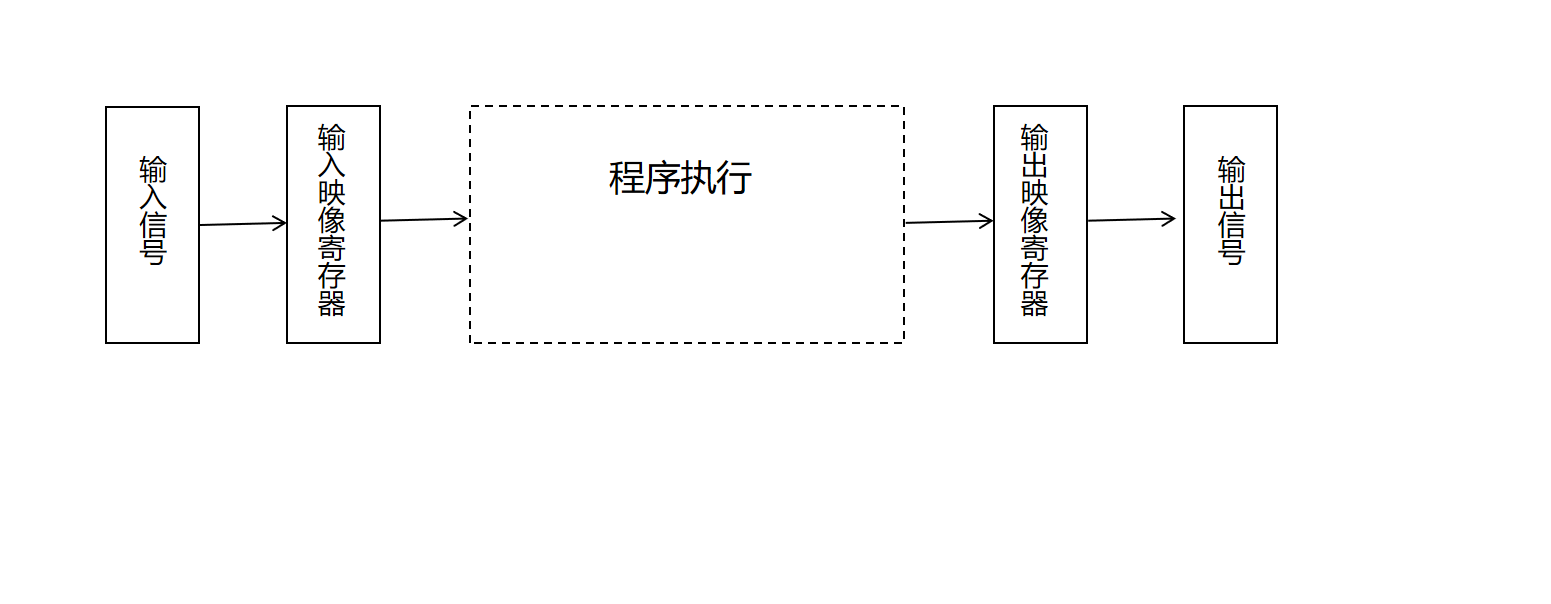
- Execution phase description, as shown in the following table:
| Execution Phase | Phase Description |
|---|---|
| Input sampling stage | At the beginning of each scan cycle, the PLC detects the status of the input device and writes the status into the input image register area. The PLC reads the input signals of all input terminals in scanning mode and stores each input status in the corresponding input image register. At this time, the input image register is refreshed. |
| Program execution phase | In the program execution phase of the scan cycle, the PLC reads the status and data from the input image area or output image area, performs corresponding operations, and saves the results in the output image area. |
| Output refresh stage | PLC sends the output variables in the output image area to the output latch, and then the latch generates the control output of this cycle through the output module. |
The above three stages, the implementation of the completion of a work cycle, analogous to the continuous cycle of the task, that is, as long as the CPU has the resources to perform these three cycles; cycle cycle task, is in accordance with a certain cycle time to perform these three cycles.
4.1.6 Task execution timeout monitoring
- Watchdog: The watchdog can be understood as a timer, defining the time monitoring of the task, and monitoring the timeout failure that occurs when the program in the TASK is executed. The watchdog mainly performs timeout monitoring for TASK.
- After using the watchdog, the system will perform the following processing:
- Interrupt the current TASK execution and system call related timeout TASK. After the timeout event TASK is executed, the TASK that was interrupted due to timeout continues to run and is also restarted during TASK monitoring. If the same task times out three times in a row, the PLC switches to STOP mode.
- If the task timeout event TASK does not exist. PLC goes directly to STOP mode
- The system cannot automatically delete user programs and tasks
- The cycle period TASK execution event exceeds 3 times the set watchdog time. PLC goes to STOP mode
- If the TASK execution times out, report the TASK timeout event to the diagnostic buffer
- If TASK execution timeout monitoring (watchdog) is enabled and not selected, the PLC system does not interfere with TASK execution.
- Continuous cycle TASK, the default watchdog is enabled (can be modified)
- Fixed period cycle TASK, the default watchdog enable is not checked (can be modified)
- Event TASK, watchdog is not checked by default (can be modified)