6.1.2 LD Basic Information
6.1.2.1 LD basic elements
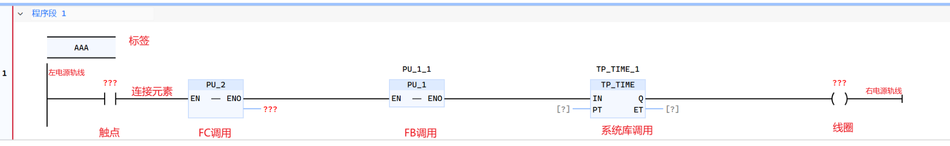
- The elements used in the ladder diagram LD language are roughly as shown in the figure below: including some basic elements such as power lines, labels, connection elements, calling functions, calling function blocks, contacts, and coils. For specific usage, please refer to LD Basic Instructions
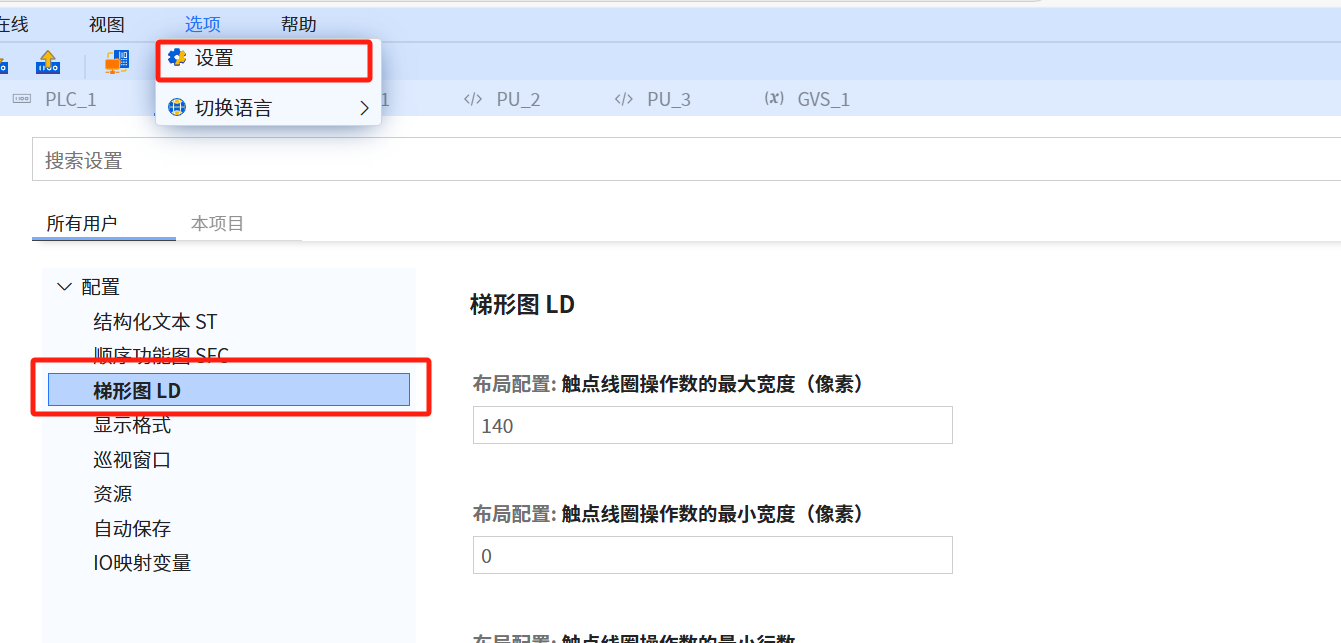
- Ladder diagram LD language modification settings, as shown in the figure below:
6.1.2.2 LD contact
-
For specific usage, please refer to Boolean Command Contact
-
A contact is an element that passes status to the horizontal connection on its right
-
The standard contact is equal to the Boolean AND of the contact state and the state of the left horizontal connection. When the status of the graphic element on the left side of the contact is OFF, no matter what the status of the contact is, its status cannot be transferred to the graphic element on the right side of the contact, that is, the status of the graphic element on the right side is OFF. The exception is the inverting contact
-
Contacts do not modify the value of the associated Boolean variable. The contact can be a Boolean variable, or it can represent an input instruction, and the result is a Boolean quantity after a certain operation
-
Static contacts can be divided into normally open contacts and normally closed contacts. In the initial de-energized state of the coil (associated Boolean = 0), the normally open contact is open and its status is OFF; while the normally closed contact is closed and its status is ON
-
The relevant contact symbol table is as follows:
| Serial Number | Description | Operating Instructions | Explanation |
|---|---|---|---|
| Static contact | Static contact, when programming, right-click the contact to change the properties of the contact | ||
| 1 | Normally open contact |  If the state of the associated Boolean variable ON, then copy the status of the left horizontal line to the right horizontal line. Otherwise, the state of the right horizontal line is OFF Remarks: The contact state is the state of the Boolean variable | 1. The activation of the normally open contact depends on the signal state of the relevant operand. When the signal state of the operand is "1", the normally open contact will close, and the output signal state is set to the state of the input signal 2. When the signal state of the operand is "0", no The normally open contact is activated and the signal status of the instruction output is reset to "0" |
| 2 | Normally closed contact |  If the state of the associated Boolean variable OFF, then copy the status of the left horizontal line to the right horizontal line. Otherwise, the state of the horizontal line on the right is OFF Remarks: The contact state is not | 1. The activation of the normally closed contact depends on the signal state of the relevant operand. When the signal state of the operand is "1", the normally closed contact will open, and the signal state of the instruction output is "0". 2. When the signal of the operand is "0", the normally closed contact will not be enabled, and the signal status of the input will be transmitted to the output |
| Conversion pulse-detection contact | |||
| 3 | Positive transition pulse-detection contact |  yyy When the state of the left horizontal line is ON and the transition of the relevant variable from OFF to ON is detected, the period from one evaluation of this element to the next evaluation is completed. The state of the horizontal line is ON. At all other times, the state of the right horizontal line should be OFF. Note: yyy is the Boolean value used to store the Boolean variable and move it up. The contact state is fed back by the state of the variable | Using the "positive pulse detection contact" instruction, you can determine whether the signal state of the specified operand "operand 1" changes from "0" to "1". This instruction will compare the current signal state of "operand 1" with the signal state of the last scan. The signal state of the last scan is saved in the edge storage bit "operand 2". If the instruction detects that the logical operation result changes from "0" to "1", a rising edge has occurred |
| 4 | Negative transition pulse-detection contact |  yyy When the state of the left horizontal line is ON and the transition of the relevant variable from OFF to ON is detected, the period from one evaluation of this element to the next evaluation is completed. The status of the horizontal line is ON. At all other times, the status of the horizontal line on the right should be OFF Note: yyy is used to store the Boolean variable up. Its Boolean value is used, and the contact status is fed back with the status of the variable | Using the "negative pulse detection contact" instruction, you can determine whether the signal status of the specified operand "operand 1" changes from "1" to "0" .This instruction will compare the current signal state of "operand 1" with the signal state of the last scan. The signal state of the last scan is saved in the edge memory bit "operand 2". If the instruction detects that the logical operation result changes from "1" to "0", a falling edge has occurred |
| 5 | Inverting contact |  Invert the state of the left horizontal line and copy it to the right horizontal line. If the left horizontal line is ON, the state of the right horizontal line is OFF; If the left horizontal line is OFF, the state of the right horizontal line is ON; Note: The state of this contact is consistent with the state of the left horizontal line | Use the "Negation" instruction to invert the signal state of the logical operation result. If the signal state of the instruction input is "1", the signal state of the instruction output is "0". If the signal state of the instruction input is "0", the output signal state is "1" |
6.1.2.3 LD coil
-
For specific usage, refer to Boolean command-coil
-
The coil stores the state or transition-related function of the left horizontal line into the relevant Boolean quantity, and copies the state of the left horizontal line to the right horizontal line without modification. In other words, the value of the coil-related variable does not affect the left and right connection status
-
The relevant coil symbol table is as follows:
| Serial Number | Description | Operating Instructions | Explanation |
|---|---|---|---|
| Momentarycoils | Momentary Coils | ||
| 1 | Coils |  The state of the horizontal line on the left is copied to the associated Boolean variable and on the right horizontal line. Remarks: The coil status is the status of a Boolean variable | The signal status of the logical operation result of the coil input is "1", and the signal status of the specified operand is set to "1". If the signal status of the coil input is "0", the bit of the specified operand decreases to "0" |
| 2 | Negated coils |  The state of the left horizontal line is copied to the right horizontal line. The state of the left horizontal line is copied to the associated Boolean variable after the meal. Note: The coil state is the state of the Boolean variable | The result of the logical operation can be inverted and then assigned to the specified operand. When the logical operation result of the coil input is "1", the operand is reset. When the result of the logical operation of the coil input is "0", the signal state of the operand is set to "1" |
| Latchedcoils | Latched Coils | ||
| 3 | Set (latch) coil |  When the left horizontal line is in the NO state, the associated Boolean quantity is set to the NO state and remains in this state until the coil is reset Remarks: This coil state is the state of the Boolean variable | can be specified The signal status of the operand is set to "1", and the instruction is executed only when the logical operation result of the coil input is "1". If the signal flows through the coil, the specified operand is set to "1". If the result of the coil input is "0" (no signal flows through the coil), the signal state of the specified operand remains unchanged |
| 4 | Reset (unlock) coil |  When the left horizontal line is in the ON state, the association The Boolean variable is reset to the OFF state and remains in this state until the coil position Remarks: This coil state is the state of the Boolean variable | resets the signal state of the specified operand to "0". This instruction is executed only when the logical operation result of the coil input is "1". If the signal flows through the coil, the specified operand is reset to "0". If the result of the coil input is "0", the signal state of the specified operand will remain unchanged |
| 5 | Positive transition pulse-detection coil |  YYY When detected When the horizontal line on the left transitions from OFF to ON, the state of the associated Boolean quantity is ON from one evaluation of this element to the next evaluation. The state of the left horizontal line is always copied to the right horizontal line. Remarks: YYY is a Boolean value used to store one period on the left horizontal line. This coil state is the state of the pulse Boolean variable | You can use the "positive conversion pulse" instruction to set the specified operand "operand 1" when the logical operation result changes from "0" to "1". This instruction compares the current result with the last query result of "operand 2" stored in the edge storage bit. If the instruction detects a change from "0" to "1", a rising signal edge has occurred. Every time an instruction is executed, the rising edge of the signal will be queried. When a rising signal edge is detected, the signal status of "operand 1" will remain set to "1" for one program cycle. In all other cases, the signal state of the operand is "0" |
| 6 | Negative transition pulse-detection coil |  YYY When detected When the left horizontal line transitions from ON to OFF, the state of the associated Boolean variable is ON from one evaluation of this element to the next evaluation. The state of the left horizontal line is always copied to the right horizontal line. YYY Remarks: YYY is a Boolean value used to store one period on the left horizontal line. The coil state is the state of the pulsed Boolean variable | You can use the "negative conversion pulse" instruction to set the specified operand "operand 1" when the logical operation result changes from "1" to "0". This instruction compares the current result with the last query result of "operand 2" stored in the edge storage bit. If the instruction detects a change from "1" to "0", a falling signal edge has occurred. Every time an instruction is executed, the falling edge of the signal is queried. When a falling signal edge is detected, the signal status of "operand 1" remains set to "1" for one program cycle. In all other cases, the signal state of the operand is "0" |
6.1.2.4 LD Programming
| Access | Execution Sequence | Execution Rules |
|---|---|---|
| All data types supported by the application software can be accessed as operands | Starting from the top rung, one rung is completed, and then the next rung is executed | 1. There is no connection between the rungs 2. Each program segment Only one jump instruction can be inserted into |
| All supported declared instances of the application software can be accessed | 1. A program segment has a sequence number, and can be assigned a title, comment and jump label 2. The availability of title and comment areas can Open or close the LD editor dialog box through "Options", settings | 3. Only one jump label can be inserted into each program segment, and at the beginning of the program segment 4. Jump instructions are allowed to jump to This program segment label or other program segment labels |
-
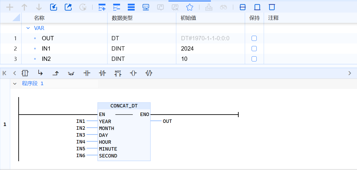
LD programming window
-
Components of the programming window (stated from top to bottom):
- Tab page toolbar allows for quick and easy code expansion, file import and export, etc.
- Declaration area form
- Code area, favorite bar, program segment name
-
For the basic instructions of LD programming, please refer to Basic Instructions-LD
-
For LD programming system library instructions, please refer to System Library Description
- Prohibit energy flow from right to left, and cannot create branches that may cause reverse energy flow
- No short circuit
- Except for contacts, coils and Function block can be used to terminate the writing of a ladder program
- Constants or constants (such as TRUE or FALSE) cannot be assigned to storage bits under various types of coils or pulse contacts
- Conversion pulse-detection coils cannot be arranged directly on the leftmost side of the ladder because they require logic operations in advance
- If the element of a horizontal line is not closed with the right bus, the ontology and program are incomplete, and a compilation error will be reported (Jump and return come with the default right bus by default)
- If the BOOL input pins of a Function block (except the first one) need to be connected, they can only be connected to the independent rungs coming out of the left bus. BOOL output pins (except the first one) cannot be wired. The first input pin is not allowed to be directly connected to the left bus