13.1 Axis Configuration
The axis is the mechanical transmission part in a servo system. The servo motor transmits the rotational motion to mechanical equipment through the axis. The axis can be connected to various working components, such as robotic arms, machine tools, conveyors, etc., and transmits the rotational force generated by the servo motor to these components to perform specific tasks.
In a servo system, the control signal for the servo motor comes from the controller. The controller sends corresponding control signals to the servo motor based on the set target values (such as position or speed). The servo motor adjusts its output torque, speed, and other parameters based on these signals, and drives the load (such as a robotic arm, robot joints, or machine tool components) through the axis for precise motion control.
- All parameters of “Process Control” - “Axis Attributes” can only be modified in the PLC stop state; if the axis attributes are modified in the PLC running state and then incrementally downloaded, the modification will not take effect. If you modify the axis attributes while the PLC is running and then download them incrementally, the modification will not take effect.
13.1.1 Axis configuration environment
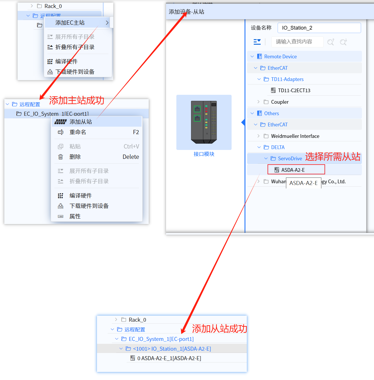
13.1.1.1 Add remote station
- Add EC master
- Add ASDA-A2-E slaves
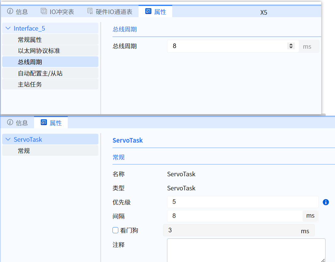
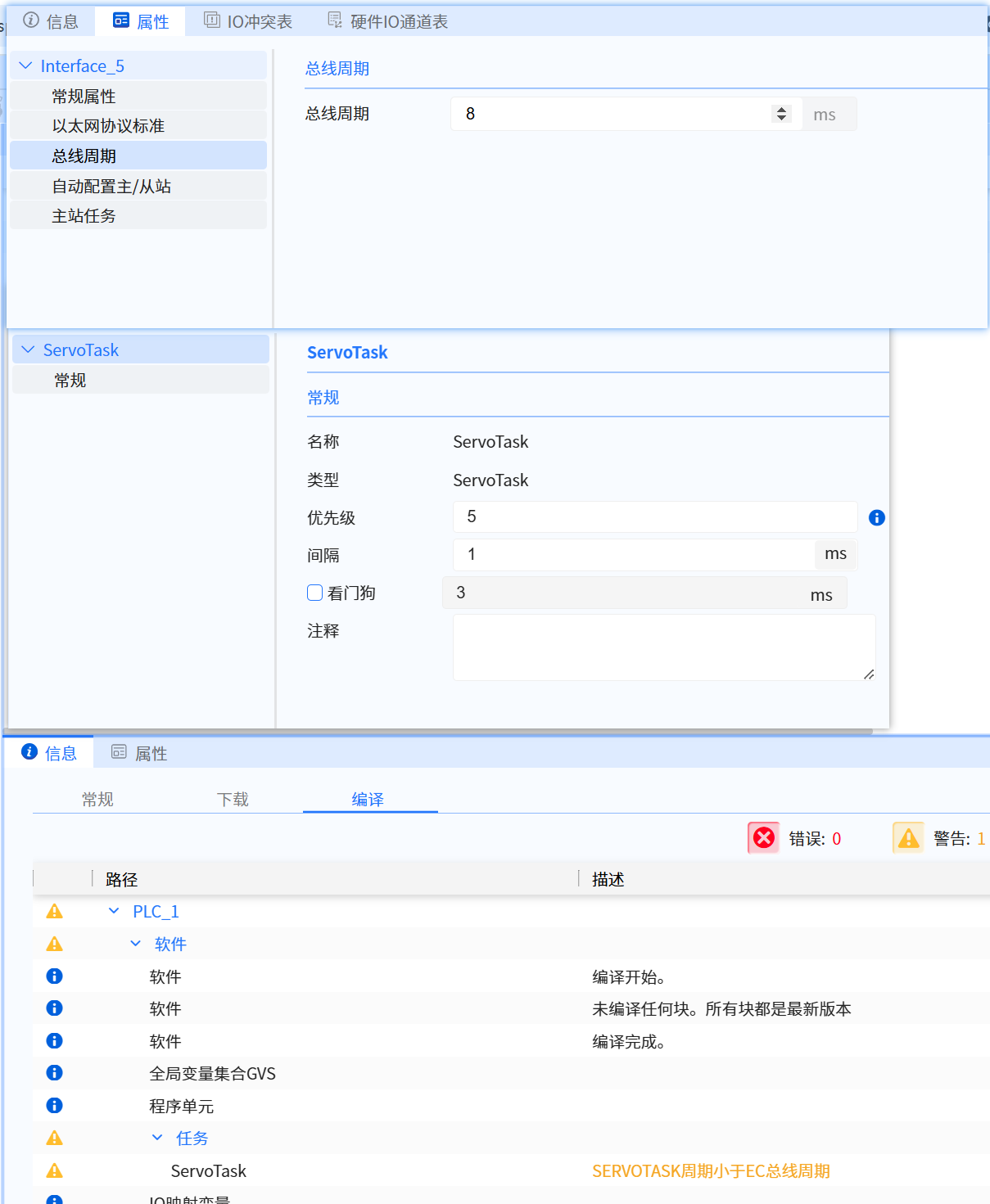
- Set the bus cycle to match the ServoTASK cycle interval
- The above three operations are shown in the following figure
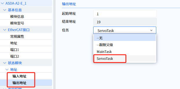
- Slave properties configuration:
- support servo device parent (EC slave interface) task binding “ServoTask” (default is “-follow parent”)
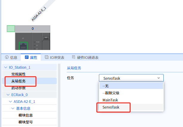
- support servo device (input/output) task binding “ServoTask” (default is “-follow parent”).
Currently Supported Servo Drive Brands:
- Delta
- Lenze
- Inovance
13.1.1.2 Create axis
- The maximum number of axes allowed by Baosky PLC (T3): 16
- The maximum number of axes allowed by Baosky PLC (T4): 32
- Please consider the following factors when creating an O&C project:
- For O&C applications where consistency is important, it is recommended that the same brand of servo drives be used
- For O&C applications with high performance requirements (electronic gears, etc.), it is recommended that all master and slave axes be located on the same EtherCAT bus
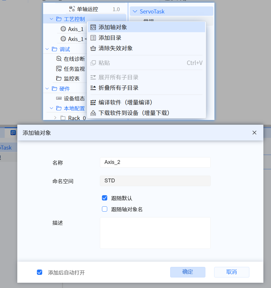
- After creating a new project, select Process Control on the left toolbar, right-click to pop up the directory , select "Add Axis Object", and the "Add Axis Object" dialog will pop up, as shown in the following figure:
- The namespace name can be modified when creating a project. When "Follow Default" and "Follow Axis Object" are unchecked, user can input the namespace as needed
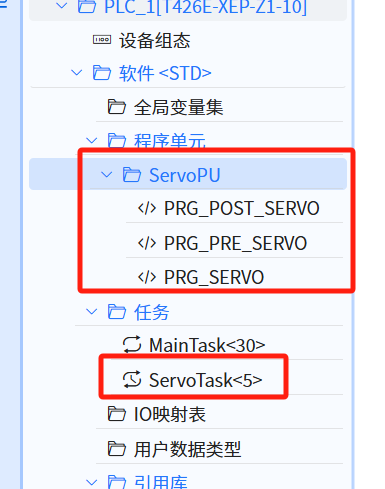
- After the first axis is added, the left toolbar, by default, creates ServoPU under the program unit node and ServoTask under the task node, as shown in the following figure:
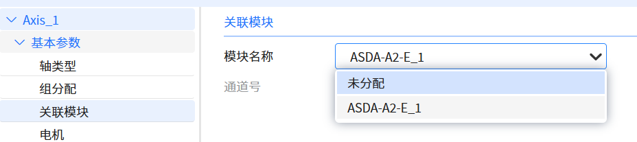
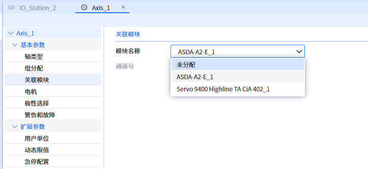
- Correlate Module,in this case , the ASDA-A2-E_1 module is associated , as shown in the figure below
13.1.1.3 Invoke function block
The user is strictly prohibited from using the function blocks (TC_INITSERVOFB, TC_INITSERVOFBFINISH, TCAXISRTDATA, TCDRIVERTDATA, TC_SERVOFB, TC_STOPSERVOFB) contained in the system-generated ServoPU (PRG_POST_SERVO,PRG_PRE_SERVO,PRG_SERVO) in any way
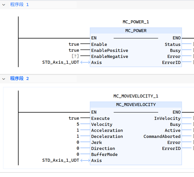
- MC_POWER, assign enable to TRUE to enable the axis
- MC_MOVEVELOCITY, let the axis rotate at a maximum speed of 5u/s and an acceleration of 1u/s2
- User can add responsive commands as needed, please refer to Single-Axis Motion Control
- As shown in the figure below
The input parameter “Axis” of the function block can only be modified in the PLC stop state; if the input parameter “Axis” of the function block is modified in the PLC running state and then incrementally downloaded, the axes of the function block are still bound to the axes before the modification.
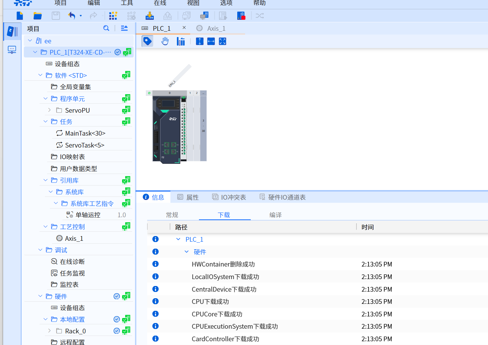
13.1.1.4 Download
- Select the required Baosky PLC, as shown in the figure below
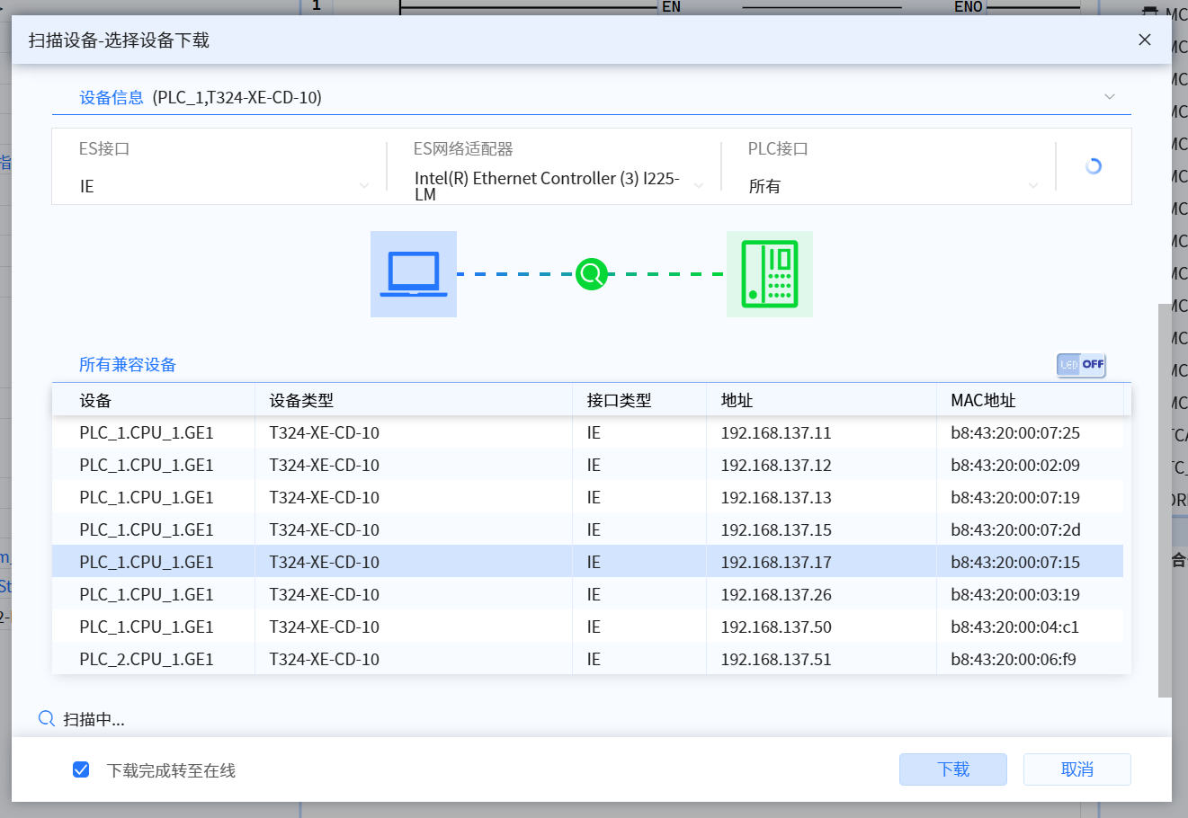
- Download successfully, as shown in the picture below
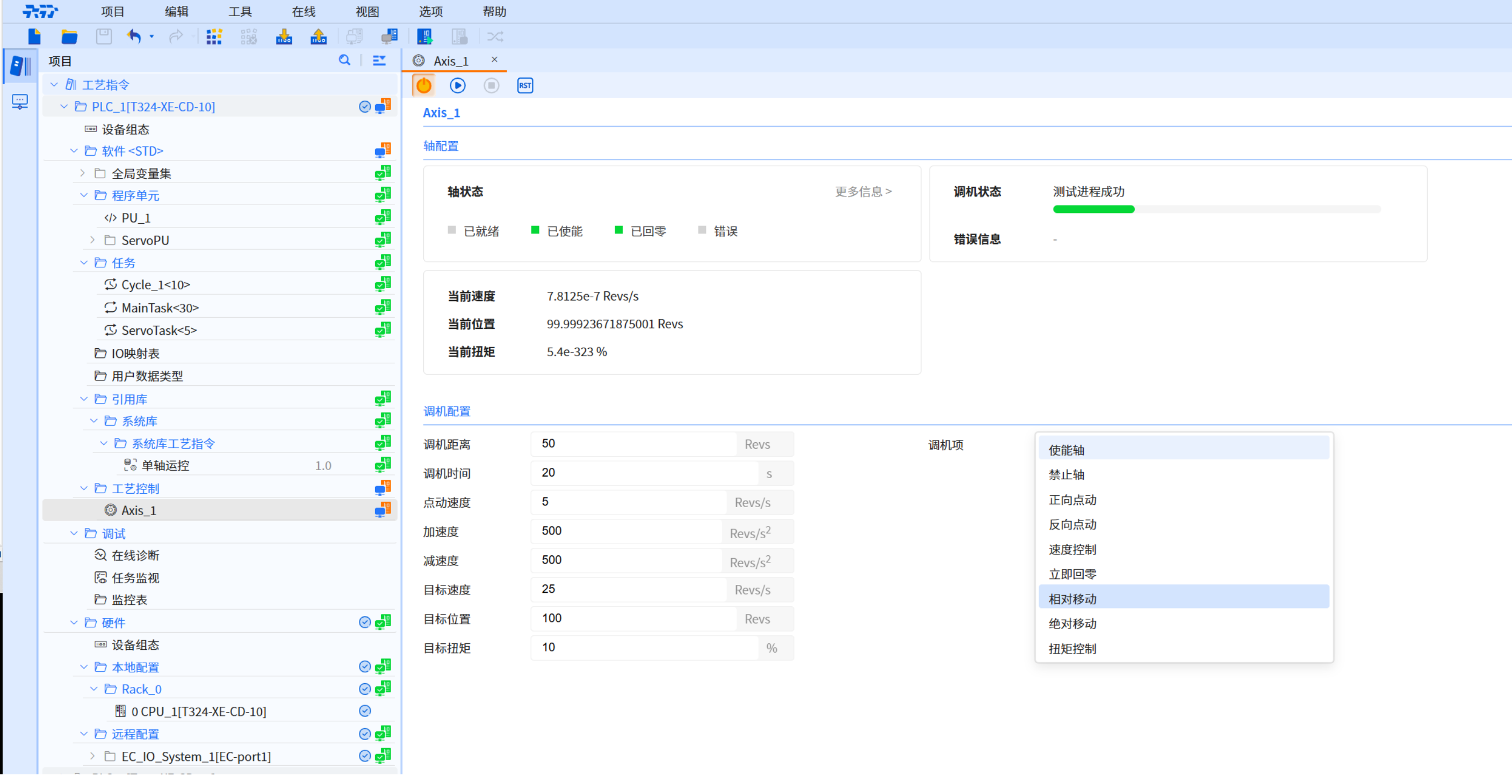
13.1.1.5 Run successfully
- Click the Enable Tuning button and the execution is successful, as shown in the figure below
13.1.2 Axis scheduling
- Axis scheduling gives user a way to configure drives to run at different update rates, working on both real axis (associated with the drive) and virtual axis. By using axis scheduling, user can optimize controller, network, and drive performance. Different O&C applications may have different performance requirements
- When adding a axis object for the first time, Baosky IDE will automatically create ServoPU and ServoTask. The interval time and priority of ServoTask (the smaller the value, the higher the priority) determine the cycle time and priority of axis scheduling
- It is recommended to set the ServoTask interval time to the same value as the EtherCAT bus cycle setting process, as shown in the figure below:
- When the period is set to different values, it may cause unstable running
- When the period is set to different values, a compilation warning will be caused, as shown in the figure below
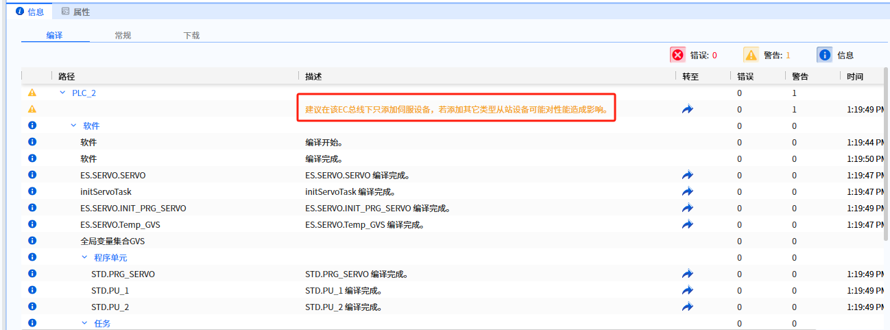
- If a servo or other slave device is added to the EC/PN bus, a compilation warning is reported when compiling the hardware.
13.1.3 Basic parameters
The key to better use of axis-related motion control commands lies in understanding the parameters of different control modes and their optimization methods. By reasonably adjusting the control parameters such as position, velocity, acceleration, etc., and choosing appropriate algorithms and hardware configurations, the stability, accuracy and response speed of the system can be effectively improved. In addition, experimentation and debugging are important means to improve the control effect. The following content introduces the relevant parameters
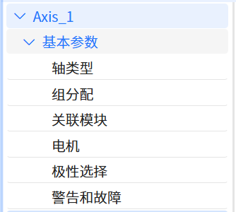
- The basic parameter UI interface is shown in the figure below
13.1.3.1 Axis type
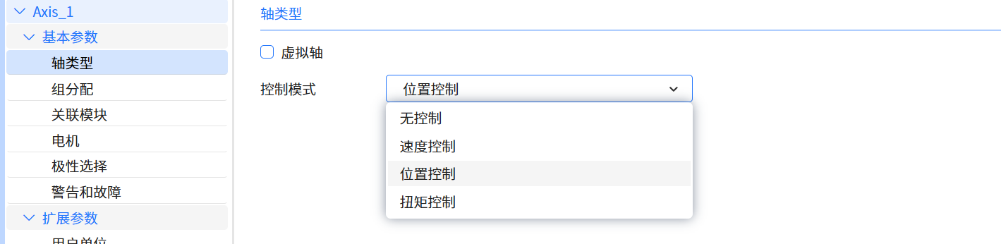
- Baosky PLC supports virtual axis and real axis
- The real axis requires the axis object to be associated with the actual servo device
- The virtual axis does not need to be associated with an actual servo device and only simulates operation within the PLC
- Both virtual and real axis support speed control and position control
- The axis type parameter UI interface is shown in the figure below
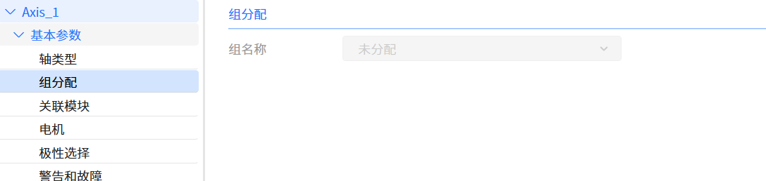
13.1.3.2 Group assignment
- The group allocation parameter parameter UI interface is shown in the figure below
13.1.3.3 Associated modules
- The associated module parameter parameter UI interface is shown in the figure below
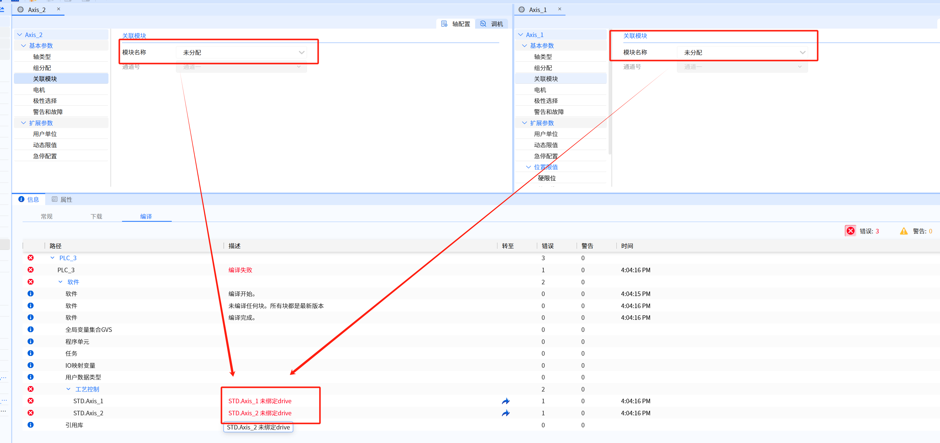
- The real axis requires the axis object to be associated with the actual servo device. If it is not associated, Baosky IDE will compile and report an error, as shown in the figure
13.1.3.4 Motor
- The motor parameter UI interface is shown in the figure below
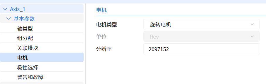
- Resolution: motor feedback resolution, default value is 0 (when module is not assigned). The value of the resolution can be edited only if the associated module selects Lenze servo, with a value range of 1 to 8,388,608.
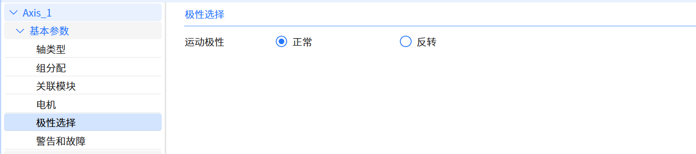
13.1.3.5 Polarity Selection
- Motion polarity can be used to switch the direction sense of the motion control system. The normal setting keeps the sign and actual signal value of the motion control command unchanged from the value in the drive control. The invert setting flips the sign of the command signal value to the drive control and inverts the actual signal value from the drive control. Therefore, motion polarity can be used to adjust the positive direction of the motion control system so that it is consistent with the positive direction on the machine
- The polarity of the motor itself determines the direction of motor rotation
- The polarity selection parameter UI interface is shown in the figure below
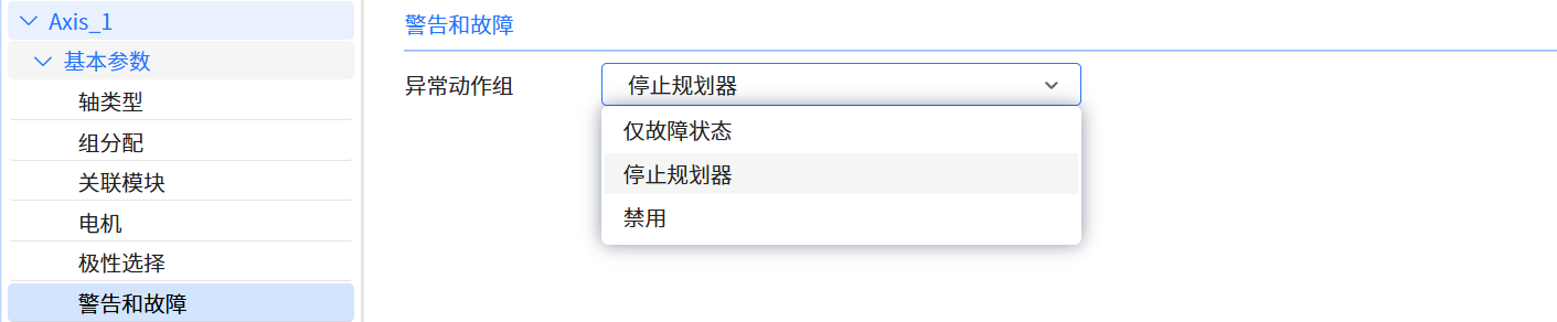
13.1.3.6 Warnings and malfunctions
- Used to specify possible operations of the operation control system when motion-related exceptions occur
| Enumeration value | Operation name | Operation description |
|---|---|---|
| 2 | Fault status only | The motion control system only reports the fault status, but does not affect the current behavior of the axis |
| 3 | Stop planner | The motion control system will report the fault status and stop the motion planner. Before stopping the planner, the axis is stopped at the specified deceleration and remains enabled |
| 4 | Disable axis | The operation control system will report the fault status, forcibly interrupt the motion planner, and stop the axis movement by disabling the axis |
- Abnormal motion situations include triggering hard limits and soft limits, etc
- Since the driver will handle some exceptions before the PLC (and may have already performed related operations), some of the above operation settings may not take effect
- For example:
- When Delta servo triggers the hard limit, the servo will stop the motor immediately. At this time, setting "fault status only" will not take effect
- The warning and fault parameter UI interface is shown in the figure below
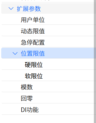
13.1.4 Extended parameters
- The extended parameter UI interface is shown in the figure below
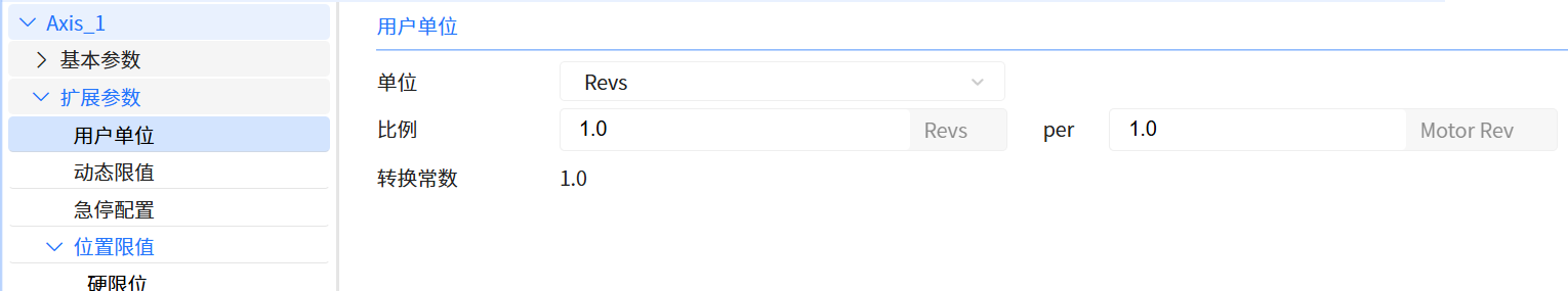
13.1.4.1 User unit
- All operation control attributes and instructions in Baosky PLC use user units, such as: position (position unit), speed (position unit/s).
- If the user changes the proportion attribute, the operation control system will proportionally convert the operation control command value (user) and the servo control value (device).
- Help users perform more intuitive and convenient operations and control in the system by setting the conversion ratio to physical quantities
- The user unit parameter UI interface is shown in the figure below
- The conversion formulas from user units to equipment units are as follows:
- Speed value (device) = Speed command value (user) * Proportional denominator / Proportional numerator
- Position value (device) = Position command value (user) * Scale denominator / Scale numerator
- For example:
- The user sets the proportion numerator = 1.0 and sets the proportion denominator = 2.0; the user speed command value = 2, then the motor runs at a speed of 4 revolutions per second (RPS)
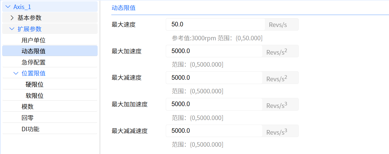
13.1.4.2 Dynamic limit
-
Servo (motor) equipment has limitations in its maximum allowed speed and maximum acceleration due to design and physical characteristics. At the same time, due to different application scenarios, users may also limit dynamic limits such as the maximum speed during the entire movement
-
The maximum dynamic load or maximum output capability that can be tolerated. Exceeding this limit will cause motor performance degradation, damage, or system instability
-
User input will be checked when the operation control instruction is executed. If the input exceeds the limit, the instruction will report an error and cannot be executed
-
The motion control planner will also limit the motion trajectory based on dynamic limits
-
The dynamic limit parameter UI interface is shown in the figure below
13.1.4.3 Emergency stop configuration
- The emergency stop signal is usually passed to the PLC as an input signal, and the PLC will execute the shutdown action according to the configured program. Many complex systems also use safety PLCs or safety relays. These devices are specially designed to handle safety signals such as emergency shutdown and equipment failure, and ensure that the shutdown operation will not be affected by external factors
- PLC status switching and PLC failure will trigger emergency stop operation of the operation control system
| Enumeration value | Operation name | Operation description |
|---|---|---|
| 0 | Deceleration to stop | The operation control system stops the axis movement at the specified deceleration, and then disables it after the axis stops |
| 1 | Disable | The operation control system will forcibly interrupt the motion planner and stop the axis movement by disabling the axis |
- The emergency stop configuration parameter UI interface is shown in the figure below
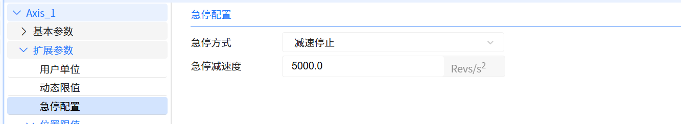
- The setting value of emergency stop deceleration will also be used to stop the planner operation when motion abnormality occurs.
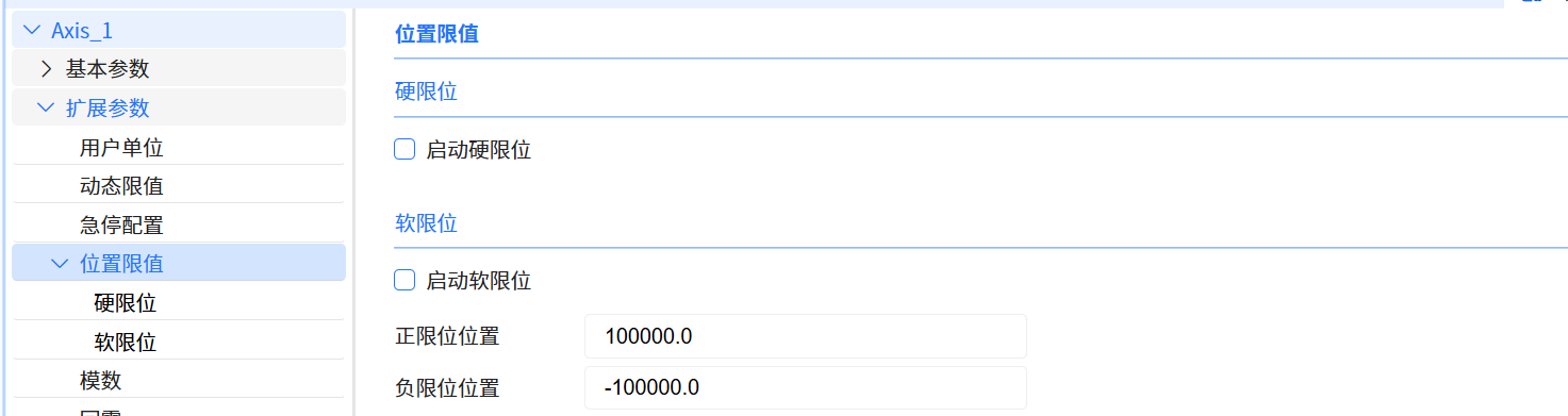
13.1.5 Position limit
-
Baosky operation control system supports stroke limit check (hard limit and soft limit). If a axis is configured with travel limit checks and the axis exceeds these travel limits, a travel limit exception condition is triggered
- Hard limit switches and soft limit switches are used to limit the "allowed travel range" and "working range" of the positioning axis technology object
- For the configured hard limit to take effect, it is recommended to check "Enable Hard Limit" and configure the DI function
- To configure the soft limit to take effect, it is recommended to check "Enable soft limit" and configure the "positive limit position" and "negative limit position"
-
The position limit parameter UI interface is shown in the figure below
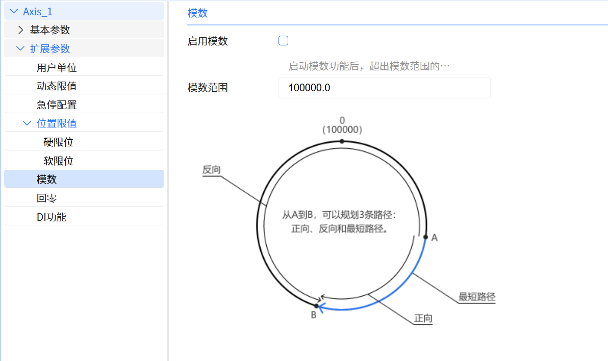
13.1.6 Modulus
-
Baosky operation control system supports analog-to-digital conversion, which is the process of converting analog signals into digital signals
-
After the "modulus" function is enabled, the position value (motor feedback value) that exceeds the modulo range will be mapped to the modulo range
-
The modulus parameter UI interface is shown in the figure below
13.1.7 Zero return
-
Zero return is used to ensure that the initial position of the motor is accurate, thereby achieving precise control
-
Absolute movement requires the establishment of a coordinate system, and successful zero return (finding the zero point/origin position) is a prerequisite for establishing a coordinate system
-
The return-to-zero operation process includes: return-to-zero speed, return speed, origin position, origin offset, and return-to-zero mode
-
The zero return parameter UI interface is shown in the figure below
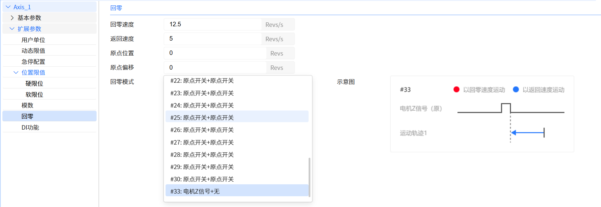
- The zero return mode selection in Baosky IDE is only used to display the trajectory diagram of a certain zero return mode and does not affect the specific zero return operation (the zero return mode is determined by the input of the zero return command)
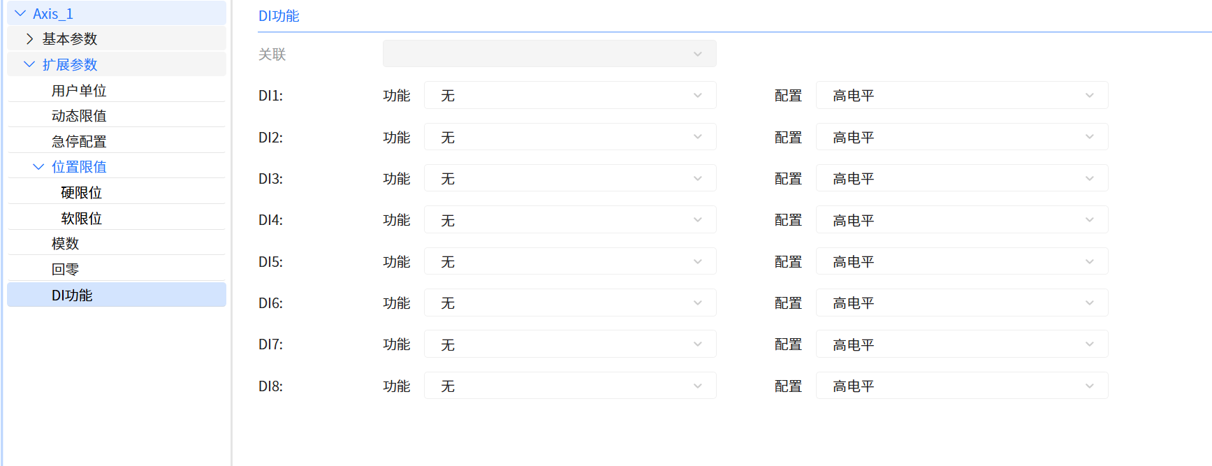
13.1.8 DI function
-
User need to configure its function options and specify the effective level according to the switch type
- Function options include positive limit, negative limit and origin switch. The positive limit, negative limit and origin switch may be used for zero return operation; the positive limit and negative limit may also be used for stroke limitation
- Level configuration includes high level and low level. Normally open switches are usually configured as high level (that is, when the switch is closed, the input signal is high level)
-
The DI function parameter UI interface is shown in the figure below