4.5 Add I/O Mapping Table
4.5.1 Introduction to I/O mapping table
- Baosky IDE uses the IO mapping table to update the IO mapping in the IO mapping table at the beginning of the cycle. The GVSIO mapping associated with the I/O input value will not change during program execution. At the same time, Baosky IDE asynchronously updates the I/O process storage area through hardware configuration. I/O mapping table realizes separation of software and hardware
4.5.2 Features and Benefits
- Users can edit or import the IO mapping table through the independent form of the editor, and associate the IO mapping of the software part with the IO address of the hardware
- The IO mapping table can be exported and saved as a CSV file, and CSV files edited using third-party table editing software (such as EXCEL, WPS, etc.) can also be imported again
- Even if the IO address corresponding to the IO mapping in the IO mapping table does not exist in the PLC hardware configuration, it will not affect the compilation of the software and the download of the program. Facilitates independent testing and operation of software
- Modify and download the IO mapping table, and user can download it without stopping the machine
- User can add variables from IO mapping table to monitor table by right clicking button in IO mapping table.
4.5.3 Adding I/O mapping table
- IO mapping plays a very important role in PLC programming. It connects and maps the IO of the PLC to external devices (such as sensors, actuators, etc.) to realize data exchange between the PLC and external devices. This section will introduce it in detail from three aspects (manual direct addition, external direct import, export IO mapping table)
4.5.3.1 Manually add
Add GVS global variable
Operation steps:
Manually add the IO mapping table directly to the project, the steps are as follows
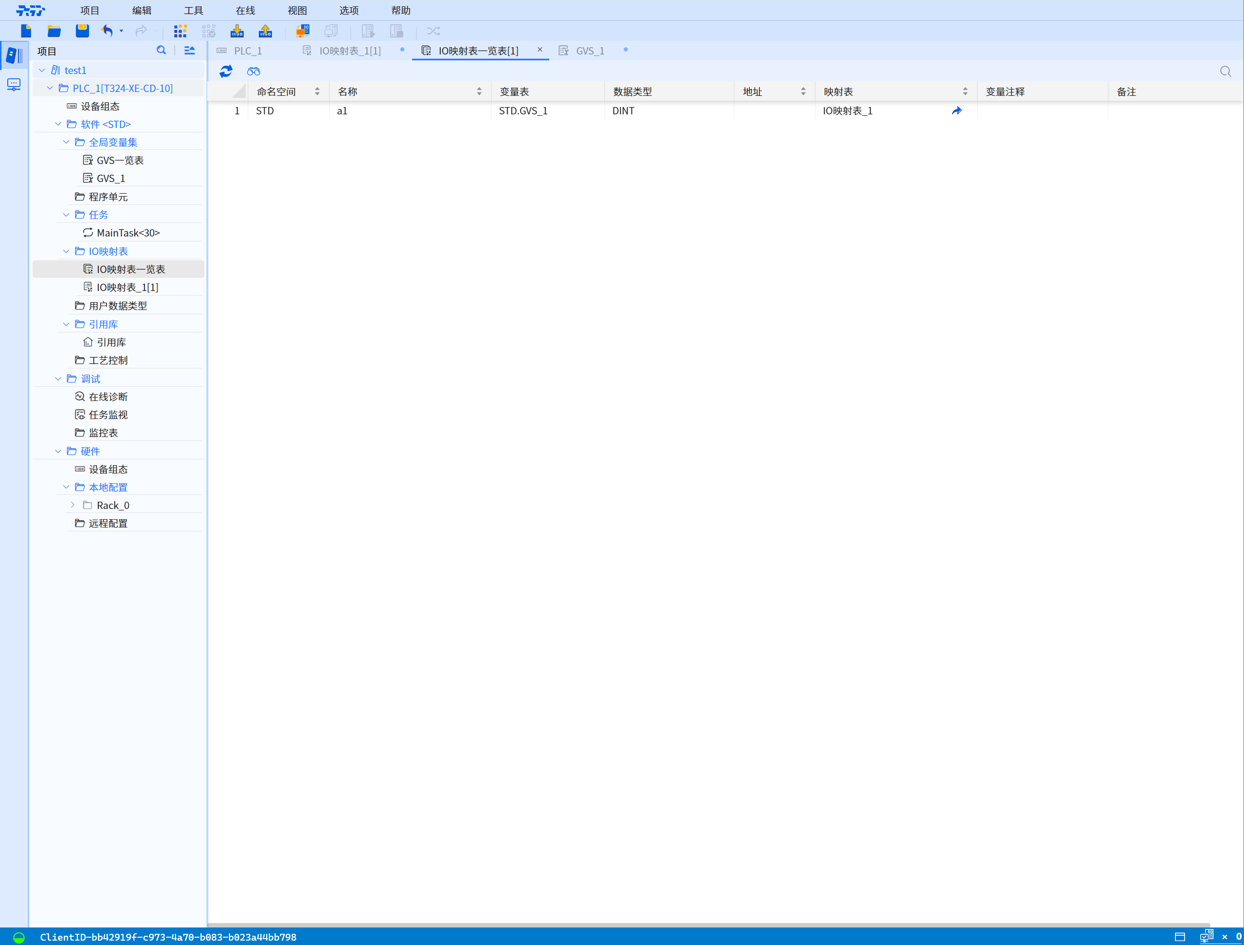
- Open the IO mapping table
- Project-->IO mapping table-->right mouse button-->Add IO mapping table
- Add IO mapping table
- Fill in the name of the IO mapping table, double-click "Add blank box" below the name, select the added GVS object or manually enter the GVS variable
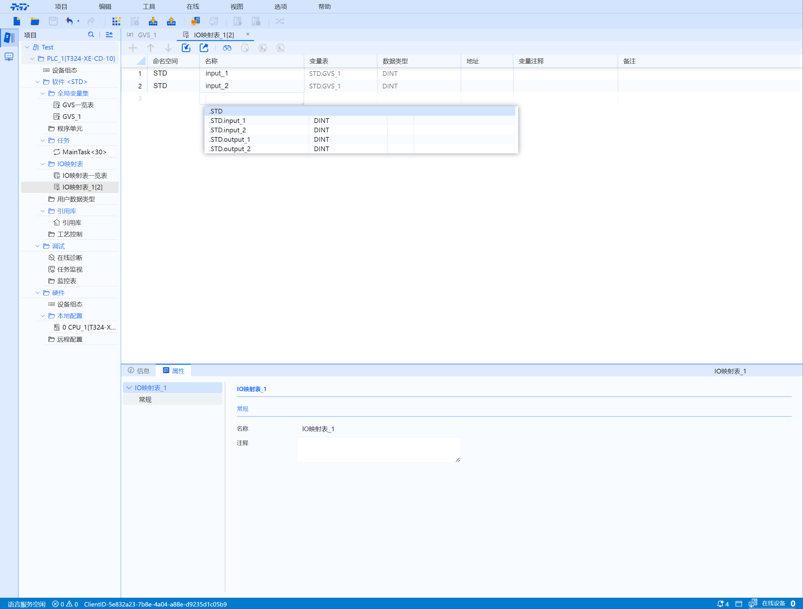
- Set the IO mapping table list
- If there are missing variable rows after adding, click "+" to add the number of rows (select the corresponding row and click "+" to add the corresponding variable row)
4.5.3.2 IO variable address binding
- The corresponding address information can be seen in the hardware IO channel table of the hardware DI and DO modules
- The direct I/O address is directly bound to the hardware IO device (set the first address of the module in the hardware configuration)
- Enter the IO address corresponding to the hardware IO address at the variable address in the IO mapping table
The data type of the variable must correspond to the data type of the hardware channel table
Jump link--> Variable Type & Data type address definition
4.5.3.3 External import added
Operation steps:
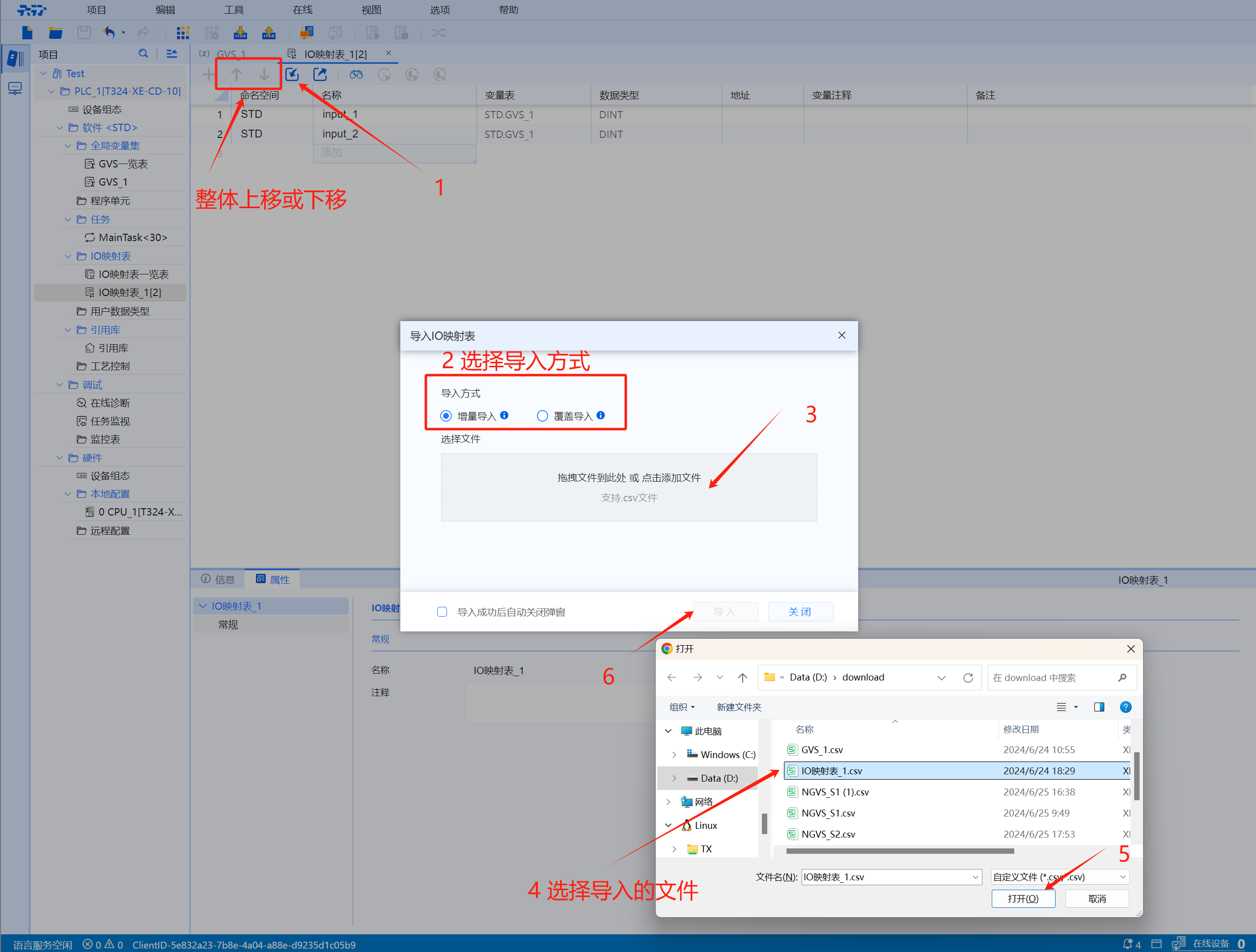
Add the IO mapping table directly from the outside, click the "Import arrow" in the IO mapping table menu bar, select the import method --> select the file (click the blank box) --> click the "Import" button ( user can choose "Automatically close the pop-up window after successful import")
- There are two ways to import:
-
Incremental import: Skip the import of variables with the same name
-
Overwrite import: Overwrite the import of variables with the same name
- In the variable table, select the entire row and click "Up Arrow or Down Arrow" to move the variable position up or down
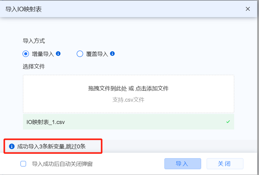
- Note: After the import is successful, the newly added and skipped variables with the same name will be displayed on the import interface
(If user choose to automatically close the pop-up window, it cannot be displayed)
4.5.3.4 Export IO mapping table
Operation steps:
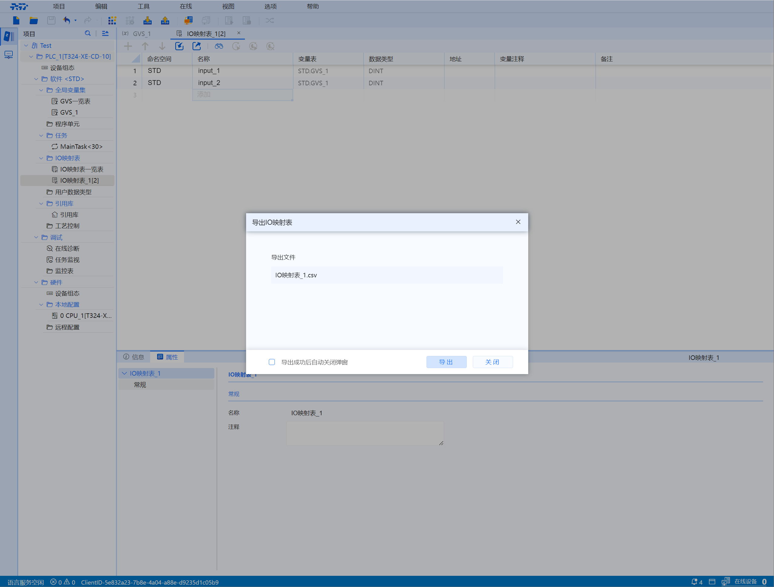
If user want to export the existing IO mapping table, click the "Export arrow" in the IO mapping table menu bar, select the export format, and click "Export" (user can select "Import successful" then automatically close the pop-up window")
4.5.4 IO mapping list
4.5.5 Add IO mapping table operation video
4.5.6 IO variable mapping table
4.5.6.1 Variable type
- In the IEC61131-3 standard, a direct representation variable refers to a variable with a fixed address prefixed by % that has a fixed correspondence with the memory, input or output physical or logical location
Mainly include the following types
| Location prefix | Description |
|---|---|
| %I | Represent input unit |
| %Q | Represent the output unit |
- Therefore, the directly expressed variables supported by Baosky IDE only support direct I/O addresses (%I and %Q are prefixes)
4.5.6.2 Data type prefix symbol and address definition
- "% direct I/O address", starting with "%", followed by the position prefix symbol (I or Q) and the data type prefix symbol (X or default, B, W, D, L) plus the address serial number
- Such as %IB0, %QW2, etc
- For BOOL quantity, the address is a.b; where a is an integer and is a byte address, and the b after the decimal point symbol "." represents the byte bit (0-7)
- Such as %IX0.0, %Q2.7, etc
The data type prefix symbols and addresses are defined in the following table:
| Prefix | Definition | Data type | Address number | Example | Type |
|---|---|---|---|---|---|
| X or default | Bit | BOOL | a.b a: unsigned integer b: 0-7 unsigned integer | X:%IX0.0, %QX0.7 Default:%I2.0,%Q2.7 | BOOL |
| B | Byte | BYTE, SINT, USINT | Unsigned integer | %IB0, %IB1, %QB2, %QB3 | BYTE, SINT, USINT |
| W | Word | WORD, INT,UINT | Unsigned integer | %IW0, %IW2, %QW4, %QW6 | WORD,INT,UINT |
| D | Double word | DWORD, DINT,UDINT | Unsigned integer | %ID0, %ID4, %QD8, %QD12 | DWORD,DINT,UDINT |
| L | Long word | LWORD, LINT,ULINT | Unsigned integer | %IL0, %IL8,%QL16, %QL24 | LWORD,LINT,ULINT |
| A | Array | Types other than BOOL | Unsigned integer | %IA+starting address (integer) %QA+starting address (integer) | BYTE, WORD, DWORD array |